|
A failed oven sensor is most often responsible for an F3 or F4 error messages on electronically controlled ovens. It can also be responsible for an F1, F2, F5, F10, F30, F31, F3-E0, F3-E1, F3-E2, F3-E3, E0-F3, E1-F3, E2-F3 and E3-F3 error message as well as just an erroneous temperature display on the control.
While the sensor probe itself is most often the cause of an F3 or F4 fault code, it is not a certainty. A problem in the wiring harness between the control and the sensor or the electronic control itself could each result in the same error codes being displayed. It will be necessary to isolate which is the actual cause of the fault condition in order to correct it.
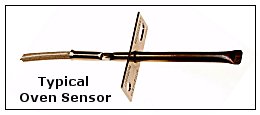
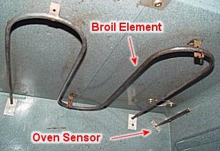
Most oven sensors have a mounting plate that is attached to the rear wall of the oven cavity interior. That mounting plate is usually held in place by 2 screws which go through it into the rear oven liner to hold it in place.
Testing the Oven Sensor
Testing of the sensor has to be performed while the problem is occurring. If the problem is present as soon as an oven function is selected and even before heating has begun, the sensor itself can be tested to see if it is within specs. The most common oven sensor currently used should measure approximately 1080 ohms when at room temperature. See below for a detailed temperature/resistance chart.
Once power has been disconnected from the appliance (do NOT just rely on the controls being off!), the sensor mounting screws can be removed. The mounting screws can sometimes be rusted or seized in place so make sure a good screwdriver is used so the screw heads don't get stripped in the process.
Once the retaining screws have been removed, the sensor should be able to be pulled (at least slightly) into the oven cavity. There should be a plastic terminal block on the wires which may have to be manipulated to get it through the hole in the rear of the oven cavity. Once through, the connector can be disconnected to access the sensor wire terminals to perform a resistance test of it.
 Some range and oven models may have the oven sensor inserted through the oven liner from the rear. If the sensor mounting screw heads are not visible from inside the oven cavity, the back panel of the range or oven may need to be removed to access the sensor mounting and harness connector to test and replace it. On a built in oven, that may involved removing the appliance from its enclosure. Some range and oven models may have the oven sensor inserted through the oven liner from the rear. If the sensor mounting screw heads are not visible from inside the oven cavity, the back panel of the range or oven may need to be removed to access the sensor mounting and harness connector to test and replace it. On a built in oven, that may involved removing the appliance from its enclosure.
Once the sensor connection is accessible, set an ohm meter on the R x 10 ohm or R x 1K ohm scale and test between the two metal terminals in the sensor's connector block.
Error Message ~ Only While in Use ~
If the error message (or an erroneous temperature display) only occurs during use, it would be dangerous to attempt to remove the sensor for testing while the oven is hot. In this case finding where the sensor circuit wires attach to the electronic control will be necessary to perform testing at that point.
How to access the electronic control's connections will depend on the design of the particular appliance. Often the temperature sensor wires will be violet colored where they connect to the control but check the particular appliance's wiring diagram to be sure.
Install an oven thermometer in the oven and operate the appliance until the problem occurs. The oven should be allowed to cycle on and off on its own at least twice. Disconnect power from the appliance (do NOT just rely on the controls being off!), access the control, isolated sensor wiring and measure the resistance of the sensor circuit. The readings should be close to what is listed in the following chart at the various oven temperatures.
| Common Oven Sensor Approx. Values |
| Temperature (F/C) |
Resistance (ohms) |
| 70°F / 21°C | ~1080 +/-4.9 |
| 100°F / 37.7°C | ~1143 +/-6.0 |
| 250°F / 121°C | ~1453 +/-8.9 |
| 350°F / 176.6°C | ~1654 +/-10.8 |
| 450°F / 232°C | ~1852 +/-13.5 |
| 550°F / 287.7°C | ~2047 +/-15.8 |
| 650°F / 343.3°C | ~2237 +/-18.5 |
| 900°F / 482.2°C | ~2697 +/-24.4 |
| *Does not apply to older GE senser # WB21X158
|
If your readings vary greatly from the chart above, the sensor may be suspect but its wiring harness is still a possibility. Once the oven has fully cooled measure the sensor circuit resistance again at the control connection. Then disconnect the sensor itself (see above) and directly measure its readings. If these two tests measure the same, it would usually indicate the wiring harness is not the problem leaving the sensor as the most likely culprit.
| 


 Often a replacement sensor will not have the same plug-in connector that the original sensor used. In such a case the wires may need to be cut and spliced together using ceramic wire nuts. The use of ceramic or porcelain wire nuts instead of plastic insure that they will not melt with the heat of the oven, especially on self-cleaning models.