|
There are many separate components in a refrigerator's defrost system that must work in concert for a frost free system to work properly. We will attempt to explain the workings using simplified electrical schematics.
The heart of the defrost system is the defrost control. The most common control is a mechanical defrost timer which is a motorized device that opens and closes several electrical contacts. Each contact can be thought of as a simple light switch but instead of a light, one connects the defrost heater circuit, another connects the cooling system. When one of these is switched on, the other is switched off. A motor on the timer (NOT illustrated) turns a cam that opens and closes these contacts at set intervals (see below for other types).
Cooling Cycle
 During the cooling mode, the defrost timer closes a contact to the compressor circuit so it will run. The circuit to the defrost heater is open. During the cooling mode, the defrost timer closes a contact to the compressor circuit so it will run. The circuit to the defrost heater is open.
While in this mode, the thermostat (a.k.a. cold control) cycles the compressor and fan motors on and off to maintain an appropriate temperature.
Defrost Cycle
The defrost timer eventually switches into defrost mode and supplies power to the defrost heater(s) to melt any frost that has accumulated on the evaporator (cooling) coil.
The cold control contacts remain closed but since the defrost timer is no longer feeding power to that circuit, the compressor does not run.
Once the defrost termination thermostat (a.k.a. defrost limit switch) senses a set temperature, it opens the circuit to the defrost heaters, shutting them off. The timer remains in the defrost cycle until the timer advances back to the cooling mode. Since the limit switch is open, the heaters are no longer on for the rest of the cycle.
Cooling Cycle
When the timer again advances back into the cooling mode, the compressor will start to run along with any air circulation fans. The defrost limit switch will remain in the open condition until it is reset by cold temperatures.
 Once a set colder temperature is reached, the defrost termination thermostat closes again. This is OK since the defrost timer is no longer supplying power to the defrost circuit, the heater does not get energized. Once a set colder temperature is reached, the defrost termination thermostat closes again. This is OK since the defrost timer is no longer supplying power to the defrost circuit, the heater does not get energized.
When the defrost timer again advances into the defrost mode, the limit thermostat will already be closed and will allow power to be supplied to the defrost heater to melt any frost that has developed on the evaporator coil again.
Fans
 Normally the interior evaporator and exterior (if present) condenser fan motors should run whenever the compressor is running and vise versa. If the timer is stopping operation of the cooling system, neither the fans nor compressor should usually be running at that time. Normally the interior evaporator and exterior (if present) condenser fan motors should run whenever the compressor is running and vise versa. If the timer is stopping operation of the cooling system, neither the fans nor compressor should usually be running at that time.
Defrost Problem Symptoms
The most common symptom of a defrost system failure is a complete and uniformly frosted (not iced) evaporator coil. Frost may also be visible on the panel covering the evaporator, usually in the rear of the freezer compartment.
Excessive frosting can be cause by the defrost heater or limit thermostat being open (ie. defective), a mechanical defrost timer sticking and never advancing into the defrost cycle or a problem in an electronic defrost control or one of its sensors failing to allow the defrost heaters to be energized.
Sometimes (but fairly rarely) both heater and cooling system can be energized by the timer at the same time. This can result in thawing then refreezing of food in the freezer compartment often leading to freezer burn on that food. In most cases the evaporator coil will remain mostly in an un-frosted state. The defrost heaters will cycle on and off as the defrost thermostat opens and closed due to the temperature it senses.
Refrigeration System Problems
NOT a defrost system problem
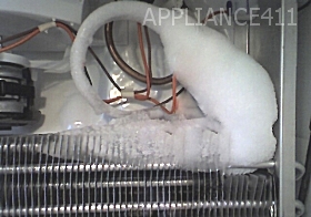
If the evaporator coil is only partially frosting (see illustration above) or a ball of ice develops on just a small area of it (see illustration below), it is usually a sign of a refrigeration system problem in which case a trained refrigeration technician will be required to determine the cause and correct it. These conditions are not caused by a defrost system failure.
NOT a defrost system problem
Defrost Component Locations
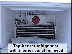
On most frost free refrigerators, the evaporator (cooling) coil is inside the freezer compartment covered by a panel. The freezer fan motor is usually in the same general area.
The defrost heater is mounted onto or woven right into the evaporator coil in the freezer. The defrost termination limit switch is usually mounted on the side of the evaporator coil or on one of the connecting tubing.
The defrost timer can be in various places including behind the kickplate at the front of the cabinet, inside the fridge compartment possibly in a control panel along with the thermostat or on older models, at the back in the motor compartment by the compressor. Some strange Kenmore refrigerator models had the defrost timer built into the icemaker unit.
The Defrost Heater
The defrost heater is basically a wire filament enclosed in a quartz, glass, aluminum or other material, tube sheath which gets hot when powered. It will either have resistance (show continuity) and be good or will have infinite resistance (no continuity) and be defective. How much resistance it has is irrelevant as its resistance will not normally change except to being open (infinite resistance) when it fails.
The Defrost Termination Thermostat
The defrost termination thermostat (aka defrost limit switch) is basically a small SPST (single pole) electrical switch which is actuated by temperature. Depending on the temperature it is, it will either have no resistance (show continuity) and be good or will have infinite resistance (no continuity) and be defective. At room temperature it will usually be open (which is normal and not a sign of being defective) and only close when it gets cold. How cold it has to be to close will depend on its particular calibration but usually near or below freezing point.
Some newer model refrigerators (Amana and Frigidaire in particular) and some older models (GE included) run power for the evaporator (freezer) fan motor through the defrost heater element and defrost limit switch. If either of those components should fail, remaining open, the fan will not run which will stop the circulation of cold air throughout the refrigerator.
On that design, the evaporator fan motor will not start running after a defrost cycle until the evaporator has had a chance to begin cooling again. While it is generally a good design idea so as not to blow the warm defrost air throughout the refrigerator, a failure in one part of the defrost system will usually render the whole refrigerator ineffective because of the lack of air flow.
Defrost Timers Types
 Early production mechanical defrost timers would go into the defrost cycle after a set amount of time. Common timing periods were 6, 8, 12 and 24 hours. This meant that say every 6 hours, the refrigerator would go into defrost whether it needed it or not. The duration of time it would remain in the defrost cycle was fixed and could be anywhere from 18 to 30 minutes depending on the timer design but it would always be the same length of time. Early production mechanical defrost timers would go into the defrost cycle after a set amount of time. Common timing periods were 6, 8, 12 and 24 hours. This meant that say every 6 hours, the refrigerator would go into defrost whether it needed it or not. The duration of time it would remain in the defrost cycle was fixed and could be anywhere from 18 to 30 minutes depending on the timer design but it would always be the same length of time.
As stated above, the defrost heaters may not be on for that full length of time, thanks to the defrost limit thermostat, but the cooling cycle would not start again until after the complete defrost duration was ended.
This original design was wasteful as the refrigerator would defrost regardless if it was necessary or not. A later design tried to help this a bit.
Cumulative Run Timers
The next design was called a 'cumulative run' timer. These timers were installed in a way were they would only count the time that the refrigerator (the compressor) was actually working. This makes sense since no frost could build up if the compressor was not running.
These later mechanical model timers would only advance the into defrost when the compressor had actually been running for a certain length of time, usually 6 to 8 hours of accumulated compressor operation.
Adaptive Defrost Control
 A later, energy saving variation is electronically controlled and called an adaptive defrost control. Not only does the period between defrost cycles change but also the time duration of the defrost cycle itself. The device is programmed to keep track of the appliance usage and how long it takes for the evaporator coil to be thoroughly defrosted. It will then calculate the amount of time required and adjust itself accordingly. A later, energy saving variation is electronically controlled and called an adaptive defrost control. Not only does the period between defrost cycles change but also the time duration of the defrost cycle itself. The device is programmed to keep track of the appliance usage and how long it takes for the evaporator coil to be thoroughly defrosted. It will then calculate the amount of time required and adjust itself accordingly.
GE's 'Mother Board'
Newer GE made refrigerators are almost totally electronically controlled. Their motherboard takes the place of both the temperature and defrost functions even controlling DC fan motors that can operate at several different speeds. On this system only the defrost heater is the same as described above. A defrost cycle is ended when a thermistor detects a temperature rise of the evaporator which is the signal to the main control to terminate the defrost and start the cooling. The termination thermostat on this appliance design only acts as a safety device to shut the heater(s) off in case of a malfunction before the plastic interior liner melts, otherwise it is never active. The control can not be manually put into defrost mode.
Other makes with 'Mother Board'
On newer models utilizing an electronic control board, it is often possible to test the functioning of the defrost heater by initiating various tests at the control. That will usually still require the freezer to be at freezing temperatures (ie. frosted up and not defrosted). How these tests are initiated varies from model to model. The instructions for your particular model will be described in your unit's 'tech sheet' which will accompany the machine's wiring diagram.
A tech sheet and wiring diagram should be found in every electronically control appliance model. Its location varies from model to model. Common locations are at the front behind the lower kickplate, at the rear by the compressor compartment or on French Door models, under the top LH or RH door hinge cover.
Mechanical Timer Testing
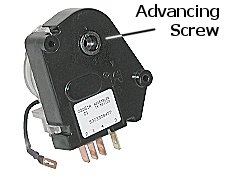 The mechanical timer types described above will usually have a screw on their underside which can be turned clockwise to manually change its present cycle. If running, slowly turning it until it clicks once should put the timer into 'defrost mode'. When in the defrost mode, turning it until it clicks once should put the timer into 'run mode'. It can be left in the defrost mode to see if it will advance by itself to the run mode (like it should in less than 30 minutes) or the defrost heaters may be able to be tested to see it they are receiving power or not at that time. The mechanical timer types described above will usually have a screw on their underside which can be turned clockwise to manually change its present cycle. If running, slowly turning it until it clicks once should put the timer into 'defrost mode'. When in the defrost mode, turning it until it clicks once should put the timer into 'run mode'. It can be left in the defrost mode to see if it will advance by itself to the run mode (like it should in less than 30 minutes) or the defrost heaters may be able to be tested to see it they are receiving power or not at that time.
 NOTE: Once the compressor has been turned off, it should be allowed to sit idle for several minutes (5-10 minimum) before attempting to restart it. This is required to allow the internal refrigerant pressures to equalize so the compressor is able to restart again without putting excessive strain on it and damaging it. NOTE: Once the compressor has been turned off, it should be allowed to sit idle for several minutes (5-10 minimum) before attempting to restart it. This is required to allow the internal refrigerant pressures to equalize so the compressor is able to restart again without putting excessive strain on it and damaging it.
Test points and how to manually switch adaptive defrost controls into the different cycles vary from manufacturer to manufacturer. For these, check the appliance's 'tech sheet' for instructions. It is usually included in the appliance's wiring diagram which is most often located behind the kickplate at the bottom front of the refrigerator or inside the control console along with the defrost control.
|